
- Need CNC prototypes? A prototype exists to fail early and cheaply. The value is not the part in your hand — it is how fast the next revision reaches your bench.
- What CNC prototyping buys you: production-intent material and tolerances without tooling, so the design you validate is the design you can actually make at volume.
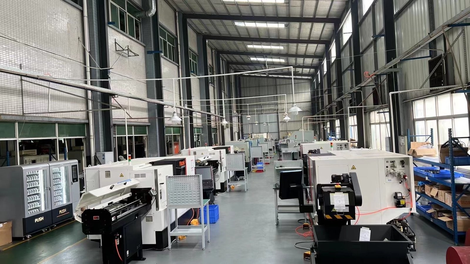
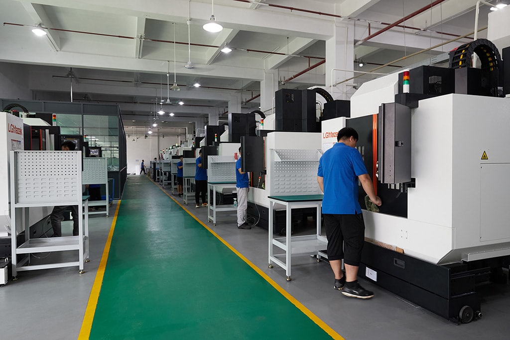
- Over 100 machines on one floor — Mazak / Brother / Tsugami / Star / Citizen class across 6,800 m², with 50+ 3-axis, 20+ 4-axis, 20+ 5-axis, 25+ lathes, 7+ grinders and 20+ inspection instruments.
- Measured, not claimed: ±0.003 mm, turning ±0.002 mm, grinding ±0.002 mm, verified on Hexagon CMMs. Per-characteristic capability is Ppk ≥ 1.67 initial and Cpk ≥ 1.33 production (≥ 1.33 general). Reports name the feature, band, sample size, sigma method and window.
- Certified under ISO 9001:2015, IATF 16949:2016 (design excluded) and ISO 14001:2015 — Dongguan Zhuohang Ltd is the invoicing entity behind them.
- Order terms: a one-piece minimum and lead times around 3, 7 or 30 days, set by part complexity.
What is a CNC prototyping service?
A CNC prototyping service machines one-off and small-batch parts from the production material so a design can be tested before tooling exists. The service is judged on how it reads the drawing — especially GD&T — and on the dimensional report that ships with the part. This Dongguan service holds ±0.003 mm milling and ±0.002 mm turning, verified on CMM.
CNC machining is the subtractive manufacturing of parts on computer-numerically-controlled milling, turning, and grinding equipment. A cutter removes material from a workpiece along a programmed toolpath to produce a part that meets a drawing-defined geometry, tolerance, and surface finish. "CNC" means the tool path is numerically controlled rather than hand-operated.
The rest of this guide turns that definition into a buyer's checklist for this shop — what to verify before you commit, and how the numbers on the drawing actually reach the part.
The discipline separates into milling (the cutter rotates and the workpiece is fed; prismatic geometry), turning (the workpiece rotates and the tool is fed; rotational geometry), and precision grinding / wire EDM (the tightest tolerances on critical features). A plant that produces CNC machined parts end-to-end runs all three.
The output of CNC machining is a part that meets the drawing — geometry, tolerance, surface finish, and material certificate — and is documented to a quality plan (FAI for general work, PPAP for automotive-bound parts, IMDS for material data). That is the answer to "what is CNC machining": a numerically-controlled subtractive process that produces a part to a drawing, with the quality documentation that lets the part enter an assembly.
- ±0.003 mm CNC milling, ±0.002 mm CNC turning tolerance; ±0.002 mm grinding tolerance, verified on Hexagon CMMs.
- GD&T-literate engineering — feature control frames, datums, material condition modifiers, and fits are read and verified, not skimmed.
- MOQ 1 piece, lead times of roughly 3 / 7 / 30 days depending on complexity.
- ISO 9001 + IATF 16949 + ISO 14001 — process control with SPC (Ppk ≥ 1.67 at the initial study on key characteristics) and full traceability.
What is GD&T, and why is it the core of a precise prototype?
GD&T is a symbolic language on your drawing that states not just the size of a feature, but its form, orientation, location, and runout, and, crucially, the datums those requirements are measured from. A simple ±0.05 mm on a hole diameter tells a shop how big the hole must be; it says nothing about where the hole must be. A true-position callout of ⌀0.1 mm at MMC relative to datums A, B, and C says exactly that, and it is the kind of requirement that separates a shop that can read the print from one that cannot.
For a prototype, GD&T does two jobs. It is the contract: it removes the ambiguity that turns into a dispute at your incoming inspection. And it is the cost driver: over-tolerancing a non-functional surface is the fastest way to double a prototype's price for zero functional benefit. A shop that helps you read your own drawing — and flags the callouts costing you the most — is a partner, not a vendor.
Here is the second-order effect most buyers miss. A prototype is a small bet placed to avoid a large one. If the prototype is machined to a misinterpreted print, the bet fails silently: the part looks right, assembles nearly right, and only fails in your test rig, on your customer's line, or worse, after the production order is already in. That is why this guide treats reading the print as the product itself — the metal is just the evidence that the reading was correct.
What are the 14 GD&T characteristics a prototype drawing uses?
GD&T defines fourteen geometric characteristics, and each one constrains a different kind of error. Knowing which one to call out — and on which feature — is the difference between a print that forces rework and one that machines clean the first time.
| Category | Characteristics | What it controls |
|---|---|---|
| Form | Straightness, flatness, circularity, cylindricity | Shape of a feature on its own, no datums |
| Profile | Profile of a line, profile of a surface | Contour of complex or free-form surfaces |
| Orientation | Parallelism, perpendicularity, angularity | Attitude of a feature relative to a datum |
| Location | Position, concentricity, symmetry | Where a feature sits relative to datums |
| Runout | Circular runout, total runout | Combined form + location error on rotating parts |
On a machined part, the ones that matter most are true position (hole patterns and dowel features), flatness and parallelism (sealing and mounting faces), perpendicularity (bearing bores and shoulder faces), and runout (shafts and journals). If your drawing only uses ± dimensions, a shop will often ask whether you really mean coordinate tolerancing or whether a position callout is what the function needs.
A useful way to think about the fourteen is as a hierarchy. Form characteristics (flatness, straightness) control a single feature with no reference to anything else. Orientation characteristics add a datum — they ask "flat relative to what?" Location characteristics add two or three datums and answer "where, exactly?" Runout ties form and location together for anything that rotates. A print that mixes these up — say, asking for flatness when the real requirement is parallelism to a sealing face — is the single most common reason a prototype comes back wrong even though every dimension on it measures in tolerance.
How do you tolerance a complex or free-form surface?

Most prints tolerance flat faces and round holes, so form and position callouts get the attention. But a growing share of prototypes carry a sculpted or swept surface — an ergonomic grip, a sealing land on a cast-style housing, a cam lobe, an impeller vane — where no single plane or cylinder describes the shape. That is what profile of a line and profile of a surface are for, and they are the most flexible characteristic in the whole GD&T vocabulary.
The distinction matters at quote time. Profile of a line controls the contour of a 2D cross-section in a specified direction; it is the lighter tool, used when the shape is a swept section. Profile of a surface controls the entire 3D surface in one callout, wrapping the shape in a tolerance band of uniform width around the nominal geometry. A surface-profile callout can replace a stack of size, form, and orientation dimensions on a complex part — one control frame instead of thirty ± dimensions — which is why it reads cleaner on the print and machines as one continuous requirement.
The band is the concept that does the work. A profile tolerance of 0.2 mm means the actual surface must lie between two boundaries, each 0.1 mm from the true profile — split bilateral around nominal unless a modifier shifts it to one side. The unequally disposed symbol (Ⓤ) is exactly what you need when material can only be added or only removed, a common situation on a sealing face or a cosmetic surface that must not stand proud of its neighbor.
| Callout | What it controls | Typical use |
|---|---|---|
| Profile of a line | Contour of a 2D section | Swept shapes, cam profiles, airfoil sections |
| Profile of a surface (bilateral) | Whole 3D surface in a split band | Sculpted housings, sealing lands |
| Profile of a surface (unequally disposed) | Band biased to one side of nominal | Material-removal-only or add-only surfaces |
Profile is also the characteristic most likely to expose a shop's inspection depth, because it is measured by scanning rather than by touching a few discrete points. A CMM that sweeps the surface along a nominal path and reports the maximum deviation tells you the surface actually fits its band; a shop that checks a handful of points and calls it good is guessing. If your prototype carries a profile callout, the question to ask is not "can you hold it" but "how do you verify it" — the answer should name scanning, not point sampling.
The cost rule is the same as everywhere in GD&T: tolerance the surface that functions, and let the rest fall to general tolerance. A 0.05 mm profile on a grip that only needs to feel right is buying scanning time you do not need, while a 0.2 mm profile on a sealing land that must not leak is rework waiting at your dock. Profile earns its keep on the two or three surfaces where shape is the function.
How do datums work, and why do they decide whether a part fits?
Every geometric tolerance is measured from a datum — a theoretically exact reference feature. A datum reference frame (typically A, B, C) locks the part's six degrees of freedom so that a measurement is repeatable and unambiguous. Without datums, "that hole must be within 0.1 of true position" has no true position to be relative to.
The practical consequence for a prototype is the 3-2-1 rule: the primary datum (usually the largest face) contacts three points, the secondary datum contacts two, and the tertiary datum contacts one. A shop that understands this will align your part the same way every time it is inspected, which is why the prototype's datum alignment, carried into production, is what keeps the part you qualify identical to the part you buy at volume. If a supplier cannot tell you which features are datums and how they align the part on the CMM, treat that as a red flag.
Datum precedence matters more than most designers assume. A, B, C is not a shopping list; it is a hierarchy. The primary datum takes the three largest contact points, the secondary takes two, the tertiary takes one. If a shop quietly reorders them — or aligns to a convenient face instead of the datum you called out — the entire tolerance framework shifts, and a hole that was within 0.1 of its true position on paper measures 0.3 out on your fixture. One concrete question to ask any shop: "show me the datum alignment you will use on the CMM for this print." A GD&T-literate shop answers instantly; a shop that hesitates is about to guess.
There is a subtlety on datum features worth knowing. Datums can carry material condition modifiers too. A datum referenced at MMC (for example, a hole used as a datum at maximum material condition) means the part may be shifted or rocked slightly to take advantage of the datum feature's departure from MMC — a legitimate technique that can save a functionally good part from being scrapped. A shop that understands datum shift can machine to the functional requirement; a shop that does not will over-constrain the part and bill you for the unnecessary precision.
How does a shop verify GD&T callouts before shipping?
A tolerance on paper is a promise until someone measures it. Our verification is a physical process, not an assumption: the part is clamped and aligned to its datum reference frame, then probed on a Hexagon GLOBAL S CMM. Each controlled characteristic — position, flatness, parallelism, perpendicularity, runout — is reported as a measured value, not a pass/fail flag.
- Hexagon CMMs (2) for true position, profile, and geometric verification, plus a gear measuring center and vision measuring machines.
- SURFCOM 1800D contour and roughness machine for surface-finish callouts, and a KEYENCE VK-X3000 laser microscope for fine surface detail.
- SPC control charts on key characteristics, with a representative length characteristic (76.1–76.5 mm) showing Cpk = 1.851 (one characteristic on one part, not a blanket capability claim).
Check the tolerance band first. Cpk is simply the band divided by the process spread, so it is relative — never an absolute accuracy score. The example here used a 0.4 mm band (76.1–76.5 mm) and held Cpk 1.851, deliberately wide. Put that same spread on a ±0.005 mm dimension and it would not pass. Demand the band, the sample size and the time window behind every capability figure.
The report that ships with the part is the evidence you would use to audit us — measured values you can check yourself, not an "OK" stamp.
Measurement order matters as much as the equipment. The part is aligned to datums before anything else is evaluated, because a form or position value is meaningless until the reference frame is locked. Then each characteristic is evaluated in the order the standard prescribes, and the deviation is written down as a signed number. A measured value of "0.013 mm" tells you the feature is near the center of its zone; a value of "0.089 mm" on a 0.1 mm zone tells you it is on the edge and worth watching at volume. A pass/fail stamp tells you neither, which is why it is the first thing a careful buyer rejects.
What tolerance should you put on a prototype, and what does it cost?
Tolerance is the steepest cost lever in prototyping, and it is almost entirely under your control. Holding ±0.003 mm (milling) / ±0.002 mm (turning) instead of ±0.05 mm means slower feeds, sharper tooling that is replaced more often, temperature control, and full inspection on every controlled feature. The discipline that saves money is simple: circle the two or three dimensions that control function, and let the rest fall to a general tolerance.
One GD&T-specific trap is worth naming. A coordinate (±) tolerance on a hole position gives the shop a square tolerance zone; a true-position callout gives a cylindrical zone, which is the correct interpretation for a round feature and grants roughly 57% more usable tolerance area at the same stated value. Specifying position correctly can make a part easier to machine, not harder, and it is exactly the kind of thing a GD&T-literate shop points out in a design-for-manufacturing review before cutting, not after.
The cost of a tolerance band is not linear. Each step down roughly trades a multiplier of cost for a fraction of the band, because the shop has to do more to guarantee the result at the edge of the distribution, not just hit it once. The ladder below is the general shape of that trade — a relative signal, not a price list, because the absolute cost depends on material, geometry, and quantity.
| Tolerance band | Typical process | Relative cost signal |
|---|---|---|
| ±0.1 mm (general) | Standard milling / turning | Baseline |
| ±0.05 mm | Careful setup, standard tooling | Modest premium |
| ±0.02 mm | Slower feeds, more tool changes | Noticeable step up |
| ±0.003 mm (milling) / ±0.002 mm (turning) | Temperature control, sharp tooling, full inspection | Significant |
| ±0.002 mm (grinding) | Grinding + CMM on every controlled feature | Highest |
The money question to ask yourself before you quote: which callouts carry function, and which are leftovers from a CAD default? A designer who over-tolerates a cosmetic face is buying precision nobody will measure. A shop that flags that callout — and tells you it is the most expensive line on the print — is doing the job you actually paid for.
What are fits, and how do they change the machining?
A fit is the intended relationship between a hole and a shaft — the clearance, transition, or interference you designed between two mating features. GD&T and limits-and-fits (ISO 286) work together: the tolerance class (such as H7/g6 for a clearance fit or H7/p6 for an interference fit) tells the shop the size range, and the geometric callout tells it how round and how coaxial that feature must be.
| Fit type | Example (ISO) | What it delivers |
|---|---|---|
| Clearance | H7/g6 | Free rotation or sliding between shaft and bore |
| Transition | H7/k6 | Light location, can be assembled with modest force |
| Interference | H7/p6 | Press-fit retention where the bore grips the shaft |
For a press-fit or a running fit, roundness and cylindricity become as important as size — a bore that is the right average diameter but oval will not hold a bearing the way the print assumes. That is why fits are specified and inspected together with the geometric characteristics, and why grinding (to ±0.002 mm) is the process that finishes the tightest of them.
Fits also set the practical floor for your GD&T. If the design calls for an H7/g6 running fit, the bore and the shaft each carry a size tolerance in the single-digit microns at small diameters, and a cylindricity or runout callout rides on top of that size. The shop has to hold size, roundness, and coaxiality in the same setup, so a running fit is rarely quoted as a simple "turned to size." It is a size-plus-geometry problem, and the shop that states that up front is the one that will deliver it.
How do you hand a GD&T prototype to production without starting over?
A prototype only earns its keep if the production run inherits it. When the prototype and production share one facility, four things carry over unchanged: the CAM programs (the production part is the same part, not a re-interpretation), the fixtures (re-fixturing is where tolerance leaks out), the datum alignment (the measurement reference stays identical), and the first-article report (the baseline production is inspected against).
This is not a promise; it is a number you can check — a 6,800 m² facility, 100+ people, and over a hundred machines across milling (3/4/5-axis), turning, mill-turn, and grinding, with ISO 9001, IATF 16949, and ISO 14001 behind it. If a shop can prototype your part but cannot tell you how it would make a thousand of the same thing on the same process, you are buying a sample, not a program.
The carry-over argument has a hidden cost you should weigh before choosing a shop. A prototype house that does not own production can still give you a good sample, but the moment you scale, the CAM programs, fixtures, and datum scheme are re-created from scratch by a different team, and the part you qualify for production is not the part you approved. That is the exact scenario where GD&T earns its keep: the print is the only portable asset between shops. If your print is incomplete and your only fidelity is "the last shop made it work," you have lost the one thing that survives the handoff.
How do you read a feature control frame, line by line?
Most prototyping errors happen before the metal is cut, and the majority of those happen inside one small rectangle on the drawing: the feature control frame. Reading it is a mechanical, learnable skill, and it is the exact skill this shop is built around. A frame carries four kinds of information, in a fixed order:
| Compartment | Typical entry | What it means |
|---|---|---|
| 1. Characteristic symbol | ⌖ (position), ⌀ flatness, ↗ runout | The kind of geometric error being controlled |
| 2. Tolerance value | ⌀0.1, 0.05 | Size of the tolerance zone; ⌀ means cylindrical |
| 3. Modifier | Ⓜ (MMC), Ⓝ (LMC), none (RFS) | Whether bonus tolerance applies as size changes |
| 4+. Datum references | A, B, C | The reference features, in order of precedence |
A frame that reads "⌖ ⌀0.1 Ⓜ A B C" therefore states: position, a cylindrical tolerance zone 0.1 mm in diameter at maximum material condition, measured from datum A (primary), B (secondary), and C (tertiary). Six characters and two symbols, unpacked into a complete machining and inspection instruction. A shop that reads that in one pass is the shop that machines the right part; a shop that skims it and machines "a 0.1 mm location" is the shop that will be explaining itself later.
The frame is also the unit of DFM. When a callout cannot be held — a position of ⌀0.02 mm across a thin, flexible wall, for example — the problem is visible in the frame itself, and the honest response is to name the compartment that fails and propose the alternative. That is what a DFM review should read like: line-by-line, compartment-by-compartment, not a generic "we can machine anything."
What do MMC, LMC, and RFS change about what the shop measures?

The material condition modifier is the most cost-relevant symbol on the print, because it decides how much tolerance the shop actually has to work with. It has three states:
| Modifier | Symbol | Effect on the tolerance zone |
|---|---|---|
| Maximum Material Condition | Ⓜ (M) | Zone applies at the feature's largest material state; bonus tolerance added as size departs from MMC |
| Least Material Condition | Ⓝ (L) | Zone applies at the smallest material state; used to protect minimum wall thickness |
| Regardless of Feature Size | (none) | Zone is fixed regardless of actual size; no bonus |
MMC is the workhorse. Take a hole specified at ⌀8.0–8.2 with position ⌀0.1 Ⓜ. At 8.0 mm (its maximum material condition, the smallest hole), the position zone is 0.1 mm. As the hole is machined larger, toward 8.2 mm, the shop gains bonus tolerance — up to 0.3 mm total at the largest size — because a bigger hole is functionally more forgiving of location error. A shop that understands MMC accepts a good part that a literal reader would scrap; a shop that ignores it over-machines the part and bills you for precision your function did not ask for.
LMC is the mirror image, and it shows up where wall thickness or edge distance is the concern — a hole that must not drift too close to an edge, or a boss that must keep a minimum web. RFS, with no modifier, means the zone never grows: the shop must hold the full tolerance at every size. RFS is the strictest of the three and should be reserved for the features that truly need it, because it is the most expensive to guarantee.
What is Rule #1 (the envelope principle), and why does it decide whether a size callout is enough?
Under ASME Y14.5, Rule #1 — the envelope principle — says that where only a size is specified, the form of a feature is controlled by its size envelope: a pin must fit within a perfect cylinder at its maximum material size, and a hole must contain a perfect cylinder at its minimum. In plain terms, a shaft drawn at ⌀10.0 ±0.05 must not only measure between 9.95 and 10.05 at every cross-section, it must also be straight and round enough to fit a 10.05 mm perfect ring.
The practical consequence: a shop working to ASME cannot pass a banana-shaped shaft just because every diameter measures in tolerance. The size callout quietly carries a form requirement, and the shop must check it. ISO GPS works the other way by default — the independence principle applies unless the envelope modifier Ⓞ is explicitly called out. Both are legitimate; the point is that the standard changes what the print means, and a GD&T-literate shop asks which standard governs your drawing instead of assuming.
This is a place where the reading really shows. Give the same print to two shops — one ASME-literate, one not — and you can get two different parts from the same numbers. State the standard on the title block, and you remove the ambiguity for everyone downstream. It costs one line on the drawing and saves a dispute at the other end.
How does geometric tolerancing differ from coordinate (±) tolerancing?
Coordinate tolerancing is the old habit: put ±0.1 on the X and Y location of a hole and call it done. It is simple, and it is wrong for round features in a specific, measurable way. A ±0.1 in X and a ±0.1 in Y describe a square zone 0.2 mm on each side. A true-position callout describes a cylinder. The two shapes accept different parts.
The square zone is too strict along the axes and too loose at the corners. A hole that is 0.14 mm off in both X and Y sits inside the square's corner (distance 0.198 mm from center) and passes coordinate inspection, yet a round pin would not enter it. A position zone of ⌀0.28 mm (the circle that circumscribes that square) has about 57% more area and is the functionally correct shape: it accepts the good parts the square rejected and rejects the bad parts the square accepted. That 57% is not a rounding error; it is the difference between a shop scrapping good work and shipping bad work.
| Scheme | Zone shape | Area (for 0.2 mm band) | Functional fit for a round feature |
|---|---|---|---|
| Coordinate ±0.1 X / ±0.1 Y | Square, 0.2 × 0.2 | 0.04 mm² | Wrong at corners, strict on axes |
| Position ⌀0.28 (circumscribing) | Cylinder, ⌀0.28 | ≈0.062 mm² | Correct |
Coordinate tolerancing also leaves the datum origin ambiguous — measured from where, exactly? Geometric tolerancing forces the answer by naming the datums. The shift from ± to position is the single most valuable correction a drawing can receive, and it is the first thing a GD&T-literate shop proposes when a print arrives with coordinate locations on functional holes.
How does surface roughness (Ra) interact with GD&T callouts?
Surface finish is a separate callout from form and location, and the two are easy to confuse. A face can be dead flat (form) but too rough to seal (finish), or mirror-smooth but not flat at all. Ra is the arithmetic average roughness, expressed in micrometres, and it is measured with a stylus instrument — in our case a SURFCOM 1800D — not inferred from how the part looks.
| Ra (µm) | Typical finish | Where it shows up |
|---|---|---|
| 0.2 – 0.4 | Ground / polished | Bearing seats, sealing faces, gasket lands |
| 0.8 | Fine machined / ground | Precision mating surfaces, O-ring grooves |
| 1.6 | Standard machined | General functional faces |
| 3.2 | Coarse machined | Non-critical faces, pre-plating surfaces |
| 6.3 | Rough | Clearance surfaces, cast-like textures |
Roughness and tolerance pull against each other. A tight Ra calls for grinding or fine finishing, which is the same process that delivers ±0.002 mm, so the two often travel together on bearing and sealing features. But a designer who stamps "Ra 0.4" on a face that only needs to be clean is buying grinding it does not need. The DFM review should flag that the same way it flags an over-tight position, because surface finish is a cost driver every bit as steep as tolerance.
There is also a functional link worth knowing: roughness is part of what makes a fit behave. A press-fit's retention depends partly on the microscopic peaks and valleys crushing together, and a running fit's life depends on a surface smooth enough not to gall. The finish callout is not cosmetic; it is part of the same functional contract as the size and the geometry.
How do GD&T callouts drive process and setup selection?
The print decides the process, not the shop's preference. Each characteristic maps to the machine and the clamping strategy that holds it best, and a shop that reads correctly will name that mapping in the quote instead of hiding it behind a price.
- True position across compound angles points to a 5-axis center, where the feature is reached in one setup and no tolerance is spent re-fixturing.
- Runout and concentricity on a round part point to a lathe, where the feature is cut around a single axis and the datum is the axis itself.
- Concentricity between a bore and milled features points to a mill-turn center, which turns and mills in one clamping.
- Tight roundness and Ra on a hardened part points to grinding, which holds size and form together.
The setup is where tolerance leaks out. Every re-clamping introduces a small, unknown displacement, and a shop that re-fixtures a part between two related features is quietly spending your tolerance budget on handling instead of machining. That is the real argument for single-setup processes, not speed, but the fact that the datum relationship survives untouched. When a shop quotes two different processes for the same part, ask why the chosen one was chosen; the answer should reference a callout, not a preference.
What does the shop need from you to read the drawing correctly?
The shop can only be as accurate as the print you send. A complete GD&T drawing removes every guess, and there is a short list of things that make the difference between a clean first article and a round of clarifying emails:
- Named datums. If the drawing has no datum reference frame, the shop has to invent one, and its guess may not be yours.
- Feature control frames on functional features. Position on hole patterns, flatness and parallelism on sealing faces, runout on journals.
- A general tolerance block. ISO 2768-m or equivalent, so the un-toleranced dimensions have a defined band.
- Material grade, heat treatment, and finish. The alloy and its condition change both the machining and the achievable tolerance.
- Critical-to-function flags. Mark the two or three characteristics that will make or break the assembly, so the shop knows where to spend inspection.
- A STEP or IGES model. The solid model disambiguates the geometry the 2D drawing cannot fully describe.
One habit pays for itself immediately: send the model and the drawing together, and state which standard governs the tolerancing. A print that invokes ASME Y14.5 means something different from one that invokes ISO GPS, and a shop should never have to ask. The closer your drawing is to unambiguous, the faster the quote comes back and the fewer surprises are waiting at your incoming dock.
What are ISO 2768 general tolerances, and when do they cover the un-toleranced features?
No drawing dimensions every feature. The ones you do not call out fall to a general tolerance standard, and ISO 2768 is the most common. It assigns a permissible deviation by feature size and by class — fine (f), medium (m), coarse (c), and very coarse (v). Class m is the usual default on machining drawings.
| Nominal size (mm) | f (fine) | m (medium) | c (coarse) |
|---|---|---|---|
| 0.5 up to 3 | ±0.05 | ±0.1 | ±0.2 |
| over 3 up to 6 | ±0.05 | ±0.1 | ±0.3 |
| over 6 up to 30 | ±0.1 | ±0.2 | ±0.5 |
| over 30 up to 120 | ±0.15 | ±0.3 | ±0.8 |
| over 120 up to 400 | ±0.2 | ±0.5 | ±1.2 |
| over 400 up to 1000 | ±0.3 | ±0.8 | ±2 |
ISO 2768 has a second part for geometric general tolerances — flatness, straightness, perpendicularity, and symmetry bands tied to the length of the feature — so that even the form of an un-toleranced face is bounded. When a drawing states "ISO 2768-m," both parts apply, and the shop knows the un-called-out dimensions are held to a defined, inspectable band rather than left to interpretation.
The takeaway for you: write the standard on the drawing. A print with scattered ± dimensions and no general tolerance block is an invitation for the shop to guess, and guessing is the one thing you are paying a GD&T-literate shop not to do.
What DFM rules does a GD&T-literate shop check before quoting?
Design-for-manufacturing is where the print meets physics, and a good shop runs a checklist before it ever quotes, because the cheapest time to catch a problem is on paper. These are general rules, not factory-specific promises, and they are the kind of thing you should be able to recognize in a DFM review:
- Wall thickness. Thin walls deflect under clamping and cutting, and they cannot hold a tight position across a long span. A feature below roughly 0.8 mm in metal is a warning sign.
- Hole depth-to-diameter ratio. Standard twist drilling is reliable to about 4–6 times the diameter. Deeper holes need pecking, gun drilling, or EDM, and the tolerance you can hold degrades with depth.
- Internal corner radius. A milled pocket cannot have a perfectly sharp internal corner; it inherits the tool radius. Calling a sharp corner forces EDM or a second operation.
- Thread depth and bottom clearance. Blind tapped holes need room past the full thread for the tap, or the hole must be specified accordingly.
- Datum accessibility. The datum features should be large, stable, and reachable on the CMM, or the reference frame the shop builds will be weak.
- Tolerance stack-up. Dimensions chained feature-to-feature accumulate error; dimensioning from a common datum removes the stack.
A DFM review that returns nothing but "looks good" is not a review. The one that matters names the two or three features that will fight the process, states what the shop will do about them, and lets you decide before any money is spent. That is the difference between a supplier and a partner, and it is visible in the first email exchange.
How does GD&T read differently across industries?
The same fourteen symbols do different work in different industries, and a shop that has seen the range recognizes the pattern. The main line — reading the print correctly — holds everywhere; what changes is which characteristics dominate and how tight the consequence of error is.
- Medical and surgical instruments. Small features, tight fits, and surface finish that is itself a functional requirement. Traceability and material identity are non-negotiable, and the finish callout is part of the design, not decoration.
- Robotics and automation. Position of bearing bores across two plates and perpendicularity of joint faces. If the bores on opposite sides are not coaxial, the robot binds; the GD&T exists to prevent exactly that.
- Semiconductor and optical equipment. Flatness and parallelism of mounting and vacuum faces, where a few microns of tilt is a functional failure. Profile of free-form optical surfaces and tight Ra travel together.
- E-bike and consumer hardware. Cost pressure drives the tolerance budget, so the GD&T concentrates on the interfaces that matter — axle fits (an H7/g6 class), rotor runout, and bearing bores — and everything else falls to general tolerance.
What this means for you: a prototyping service is not just a machine list, it is a body of experience about which callouts bite in which context. When you send a print, the shop's first read should reflect the industry logic behind it — "this is a rotor, so runout is the critical one" — because that is the difference between checking the right feature and checking every feature.
What happens when a shop misreads GD&T, and how do you spot it before you buy?
Every misread of a feature control frame produces a specific, predictable failure. Knowing the failure modes is how you recognize them in a quote or a first article, before they become a line stop. The most common:
- Square vs. cylindrical zone. The shop treats position as ± and either over-machines the part or, worse, accepts a corner-located hole that will not assemble.
- Ignoring MMC bonus. The shop holds a fixed zone at every size, charging you for precision the modifier already granted.
- Datum ambiguity. The shop aligns to a convenient face instead of the called-out datum, and the measured values are relative to the wrong reference.
- Ignoring Rule #1. The shop passes a part on size alone while the form is out of the envelope, and a banana shaft ships as "in tolerance."
- Treating ⌀ as a linear dimension. The shop drops the cylindrical zone and reads the value as a plain ± band, quietly shrinking the usable area.
The signals to watch before you buy are mostly about what the shop will not do. A shop that will not name your datums, will not produce a measured-value report, quotes from a napkin sketch, never flags a single callout, or agrees to everything without reading the print — each is a reason to keep looking. The cheapest audit you can run is a one-line test: ask the shop to read back your tightest feature control frame in its own words. The answer tells you everything.
How do you audit a shop's GD&T literacy in one conversation?
You do not need to visit a factory to separate a GD&T-literate shop from one that is guessing. A handful of direct questions, asked in the first exchange, does most of the work:
- "Read back my feature control frames." Ask for the meaning of your tightest callout — symbol, zone, modifier, datums. A literate shop answers in the standard's vocabulary.
- "Show me the datum alignment you will use." The shop should be able to say, in writing, how it will clamp and align the part on the CMM.
- "Send a sample dimensional report." It should show measured values, not pass/fail stamps. A number is evidence; an "OK" is an opinion.
- "Name the machine and the setup for this feature." The process should be justified against a callout, not a preference.
- "Verify your certificates with the registrar." ISO and IATF numbers are checkable. A shop that invites the check is behaving like a manufacturer.
Every one of these is a question we welcome on our own work, because the standard you should hold any shop to is the standard this shop was built around. Send the drawing, run the list, and see whether the answers reference the print or the brochure.
Guides
- CNC prototyping service cost in 2026 — your cost model priced against the GD&T on the drawing.
What this shop actually runs
A buyer asking for capability evidence should get a specific answer. The facility behind this guide operates 100+ CNC machines across a 6,800 m2 plant in Dongguan, China, with 100+ staff. The machine list by category:
- 5-axis machining centres (10+) - Mazak VARIAXIS I-600 (510/910/510 mm travel, 12,000 rpm, 22 kW, 71.6 N·m, 30-tool BT40) and Mazak INTEGREX I-250H S (B-axis 0.0001°, 24 kW, 124 N·m, 38-tool HSK-A63). Applied to compound-angle parts, single-setup multi-face prismatic work, and aerospace fittings where datum transfer loss is unacceptable.
- 3-axis / 4-axis machining centres (50+) - Brother SPEEDIO S500Z2N / S700Z2N (10,000 rpm, 14/21-tool ATC, 0.7 s tool-to-tool, Z-axis 2.2 G) and Mazak VCE-430A L / VCE-570C L (10,000 rpm, 118 N·m, 24-tool ATC). Applied to prismatic parts, plates, brackets, housings.
- Swiss-type turning centres (10+) - Citizen Cincom A20-3F7 (Φ20 mm, 10,000 rpm), TSUGAMI B0206-III / B0205-III (Φ20 mm, 0.1 µm), STAR SR-32JII / SR-32J Type N (Φ32 mm, 8,000 rpm). Applied to long, slender rotational parts at ±0.002 mm.
- CNC turning centres (20+) - HEADMAN T70M/1250 (720 mm swing, 117 mm bore, 3,000 rpm, BMT75 12-station turret). Applied to shafts, bushings, flanges up to ±0.002 mm.
- Wire EDM (5+) - Sodick AQ535L (550/350/300 mm travel, ±20° taper, 800 kg workpiece). Applied to hardened tool steel, internal splines, sharp internal corners that milling cannot reach.
- Inspection: Hexagon CMM + 20+ gauges - Hexagon CMM for coordinate measurement, plus vision system, profilometer, hardness tester, coating thickness gauge, XRF for material verification. The 10:1 rule (gauge 10x more accurate than the band) is applied to every feature.
- Machine highlights - VARIAXIS I-600: one-setup multi-face 5-axis + MAZA-CHECK auto-calibration; INTEGREX I-250H S: DONE-IN-ONE mill-turn, B-axis 0.0001° + Ai thermal shield; SPEEDIO S500Z2N / S700Z2N: Z-axis 2.2 G + 0.7 s ATC; Swiss-type: guide-bush switchable + 0.1 µm resolution.
Tolerance bands held: ±0.003 mm on CNC milling, ±0.002 mm on CNC turning, ±0.002 mm on precision grinding and wire EDM. Capability indices: Ppk >= 1.67 initial on key characteristics; Cpk >= 1.33 ongoing in production.
Certifications: ISO 9001:2015 (116024/A/0001/UK/En), IATF 16949:2016 (131941/A/0001/SM/En, design clause 8.3 excluded - disclosed openly), ISO 14001:2015 (116024/B/0001/UK/En). Certificates are issued to Dongguan Zhuohang Ltd (USCC 91441900MA4UWT6X39, established 2005).
Service area: Austria, Belgium, the Czech Republic, Denmark, France, Germany, Greece, Hungary, Ireland, Italy, the Netherlands, Spain, Sweden and the United Kingdom in Europe; Brazil, Canada, Mexico and the United States in the Americas; China, Israel, Japan, Singapore and Sri Lanka in Asia; Australia and New Zealand in Oceania; and South Africa in Africa. Based in China, serving customers worldwide.
Contact: Felipe Iglesias, [email protected], +86 13126536955.
Send a drawing the shop must actually read.
Email your GD&T-specified print and STEP model to [email protected] or call +86 13126536955 for a DFM review that flags every callout — and every cost driver — before cutting.
Frequently Asked Questions
What is GD&T and why does it matter for a CNC prototype?
In short, GD&T (geometric dimensioning and tolerancing) is a symbolic language that defines not just a feature's size but its form, orientation, location, and runout relative to datums. It matters because a ± dimension cannot describe how a hole must be located or how flat a face must be, and a shop that misreads a feature control frame will machine the wrong part.
What tolerance can a CNC prototyping service hold?
In short, ±0.003 mm on CNC milling, ±0.002 mm on CNC turning, and ±0.002 mm for precision grinding. Every critical GD&T characteristic is verified on a Hexagon CMM, with process capability Ppk ≥ 1.67 at the initial study on key characteristics and ≥ 1.33 on general characteristics.
Do I need to commit to volume to prototype a part?
No. The MOQ is 1 piece, so you can prototype, inspect against your GD&T callouts, and iterate before committing to a production run. The prototype's programs, fixtures, and datum alignment then carry over to production.
How is a GD&T callout verified before the part ships?
In short, The part is aligned to its datum reference frame and probed on a CMM, reporting every controlled characteristic as a measured value — true position, flatness, concentricity, runout — not a pass/fail flag. That dimensional report ships with the prototype.
Which materials can be prototyped to tight GD&T?
Aluminum (6061, 7075, 6082), stainless steel (303, 304, 316, 316L, 17-4PH), alloy and carbon steel, brass, copper, titanium, magnesium, and engineering plastics including POM and PEEK. Incoming lots are XRF-checked against the mill certificate.
Are you certified?
Yes — ISO 9001:2015 No. 116024/A/0001/UK/En, IATF 16949:2016 No. 131941/A/0001/SM/En, and ISO 14001:2015 No. 116024/B/0001/UK/En. IATF 16949 scope excludes product design under Clause 8.3.
What are the typical lead times for a prototype?
Roughly 3, 7, or 30 days, set by part complexity and the number of process steps rather than a blanket promise. Simple parts ship in about 3 days; parts with surface finishing or 10–20 process steps fall into the longer 30-day tier.
How do I request a GD&T-specified prototype quote?
Email a toleranced drawing (with datum and feature-control callouts) plus a STEP or IGES model to [email protected]. You receive a design-for-manufacturing review that flags any callout the shop cannot hold, along with the quote.
What is bonus tolerance at MMC?
In short, Maximum Material Condition lets the position tolerance grow as the feature's actual size departs from MMC. A hole specified at ⌀0.1 position with MMC gains extra tolerance as the hole is cut larger than its smallest allowed size, so a functionally good part is accepted instead of scrapped over a size-versus-location trade-off.
What is the difference between ASME Y14.5 and ISO GPS?
In short, Both are GD&T standards, but they differ in defaults: ASME Y14.5 applies Rule #1, where a size tolerance also controls form, while ISO GPS applies the independence principle unless the envelope modifier is called out. The shop reads whichever standard your drawing invokes, so a print should state its standard explicitly.
What surface roughness can the shop hold?
In short, Roughness is measured separately from form. Machining holds Ra 0.8–3.2 µm depending on process and material, and grinding reaches Ra 0.2–0.4 µm on the tightest seats.
What do ISO 2768 general tolerances mean?
In short, ISO 2768 is a general-tolerance standard for features not individually toleranced. Class m (medium) is the common default: a 6–30 mm linear dimension carries ±0.2 mm, for example.
What is profile of a surface, and when does a prototype need it?
In short, Profile of a surface controls the entire 3D shape of a complex or free-form surface in one callout, holding the actual surface within a tolerance band around the nominal geometry. It replaces a stack of size, form, and orientation dimensions on sculpted parts — housings, cams, impellers, sealing lands — and is verified by CMM scanning, which reports the maximum deviation across the surface rather than a few sampled points.
Do you use MIL-STD-105E or ANSI/ASQ Z1.4 sampling inspection?
In short, MIL-STD-105E is the U.S. military sampling inspection standard published in 1989; it specifies acceptable quality limit (AQL) sampling plans for lot-by-lot inspection.
Standards referenced on this page
- IATF 16949:2016 — Automotive quality management system standard
- ASTM E8/E8M-21 — Standard Test Methods for Tension Testing of Metallic Materials
- ISO 9001 — Quality management systems — Requirements
What makes Zhuohang worth shortlisting for CNC Prototyping Service?
Because choosing a machining partner is really a risk decision. Below are ten checks you can run on us — from a single-part order to what happens when a part is wrong.
- A factory you can visit. Behind the parts is a 6,800 m² floor in Hengli, Dongguan. Dongguan Zhuohang Ltd (USCC 91441900MA4UWT6X39), also known as Zhuohang Precision Machining Factory, has operated it since 2005.
- One system, three certificates. ISO 9001:2015, IATF 16949:2016 (design excluded) and ISO 14001:2015 all apply to the same floor, from a single CNC Prototyping Service prototype to an automotive batch.
- Numbers that bind. ±0.003 mm on milling, ±0.002 mm on turning, ±0.002 mm on grinding and wire EDM — verified on the part.
- Named equipment. Tight features come off a Mazak VARIAXIS I-600, a Mazak INTEGREX I-250H S, and Tsugami, Star and Citizen Swiss lathes.
- Numbers, not opinions. Hexagon CMM and vision checks on every lot, with capability reported as Ppk ≥ 1.67 initially and Cpk ≥ 1.33 in production, each with index, stage and sigma method.
- When a part is returned as defective. Repair or remake is free of charge, and we cover return shipping both ways.
- No duty surprises. Material certs travel with each shipment, and Section 301 / Section 232 and EU CBAM status stays current on our HS codes.
- No hand-offs. Milling, turning, mill-turn, grinding and wire EDM under one roof and one quality system, so CNC Prototyping Service parts stay in-house instead of stalling between suppliers.
- One part is welcome. Prototype and production share the same program and datum, so the sample you approve is exactly what ships when the order scales.
- DFM arrives with the quote. Within about two days you get a price and the design notes that would lower it, called out before your CNC Prototyping Service part starts.
Ready to test any of the ten yourself? Send a drawing for a 48-hour quote, or contact the team in English, Japanese, Portuguese, Spanish, French, Chinese or Cantonese.
From first article to production
- We have worked with Japanese and German customers for years.
- Long-term customers can be assigned a dedicated production line.
- A quote follows within 48 hours of receiving your drawings or samples.
- High quality at reasonable and competitive prices.
- No minimum order quantity. Start with a single part before committing to a production run.
- ISO 9001:2015, IATF 16949:2016 and ISO 14001:2015 certified CNC machining company.
- CNC machining quotes are checked by mechanical engineers and machinists on site.
- A management team committed to lifelong learning; its members have known each other for more than 20 years.
- We aim to be a long-term precision CNC machining partner, not just a supplier for one order.
- Payment terms: We accept PayPal, Western Union, credit cards, bank wire transfers and letters of credit.
- Net 30 Days, Net 45 Days, and Net 60 Days are acceptable for long-term customers.
- Founded to last. Our founders and management team built the company on sustainable operation, knowing that 100+ employees mean 300–500 family members to feed.